My PLC Ladder Logic Standard
Some old lessons from PLC land …

I love industrial PLCs, industrial automation, and especially Ladder Logic — today everyone one here in Silicon Valley is in Web, SaaS, Mobile, and Cloud engineering, but PLCs remain my first love of programming and technology.
It’s been many years since I worked in industry with PLCs, but way back in 1990 I developed a set of structured ladder logic standards that are still relevant today for high-quality ladder work. So, I wanted to share these standards with you.
Ladder Logic
Ladder logic is a graphical programming language used in industrial control systems to control machines and processes. Its name comes from the resemblance of the program’s structure to the rungs of a ladder.
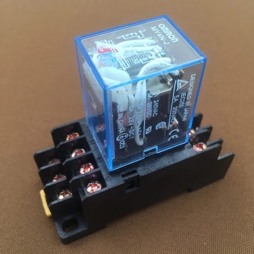
While it may seem archaic compared to modern software languages and tools, ladder logic is actually a direct continuation of over 100 years of physical relay logic used to control machinery since the dawn of electricity during the Second Industrial Revolution.
This means that engineers today still think and work in a similar way to those from a century ago when it comes to designing and implementing control systems. And while ladder logic may not be the most advanced programming language, it is still widely used and is an important tool for industrial automation. It’s also intuitive and very powerful (including changeable while its running).

Ladder logic works by using inputs, such as push buttons and sensors plus logic to control outputs, such as the motors, pumps, and lights that actually move machines and processes.
The logic of ladder programming uses the inputs to decide which outputs should be turned on or off. The structure of the ladder program is similar to relay logic diagrams, with inputs on the left and outputs on the right. The two vertical lines represent the virtual versions of the electrical power used in relay diagrams.
While the basic concept of ladder logic may seem simple, it is an important tool for industrial automation. Its graphical structure makes it easy to understand and modify, while its reliance on simple inputs and outputs makes it a reliable and efficient programming language for controlling machines and processes.
Ladder logic’s visual representation allows engineers to build logic based on simple AND, OR, and NOT logic. The structure of the program is usually tied very closely to the physical devices connected to the PLC I/O cards in various racks.
This means that the ladder program is designed to closely match the actual physical devices and processes being controlled. This makes it easier to understand and troubleshoot issues, as the program’s structure closely mirrors the physical layout of the system.
Standard Rungs
One of the most basic ladder logic blocks is start and stop latching logic for a motor. This simple example contains all the key elements of the ladder logic standard and should be used for systems simple and complex.
Simple standards help engineers avoid the temptation to create convoluted combined logic, where they try to cram ever-increasing complexity into a big rung or two. These types of programs are difficult to follow, understand, and modify safely.
Instead, by following the ladder logic standard, engineers can create programs that are easy to understand and modify. This makes troubleshooting and maintenance much easier, and helps to ensure that the system operates reliably and safely.
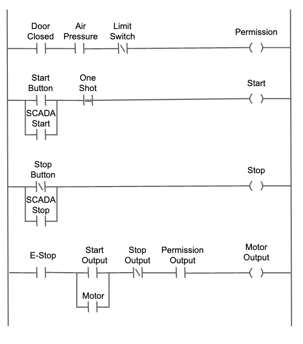
My standard rungs look like this:

Note the following key standard functions that should be present for nearly every significant on/off ladder section:
Permission Logic
In ladder logic, it’s important to separate out permission logic into a single place that makes it very clear what is needed for this motor to run. This is the logic that protects machines and people from dangerous conditions or damage, so it should be prioritized and made very clear.
Permission inputs may include guards in place, hydraulic pumps running, air pressure, and more. Since these inputs often change over time, it’s essential to have them all in one clear place to avoid making life-threatening mistakes by messing up permission and protection logic.
Adding more rungs (not shown) to detect which permission is not satisfied is also helpful. This allows operators to quickly understand why the machine won’t start, such as a door being open or a pump not running (as nothing is more frustrating than trying to start something, nothing happens, and you have no idea why). This is especially important on complex machines where troubleshooting can be time-consuming and frustrating.
Overall, separating permission logic and making it clear in ladder logic is critical for protecting machines and people and ensuring the system operates safely and reliably.
Start Logic
It’s important to separate out start logic into a separate rung to ensure that it’s clear what is starting the motor. As the system becomes more complex over time, it’s essential to have one place to manage all start inputs, such as start buttons or signals triggered by other processes.
One-shot logic (available on many PLCs) is used in the start system, ensuring that the start signal is momentary, mimicking a start button. This helps keep the machine safe by requiring all the start inputs to drop or open and then re-close to start something. This helps prevent a machine from starting suddenly when power is restored or an E-stop is reset.
By separating start logic and using one-shot logic, operators are required to do something to restart the machine, which can prevent accidents and ensure safer operations.
Stop Logic
Stop logic in ladder logic is quite straightforward — it interrupts the main rung and drops out the latch, which turns off the output. Unlike the start logic, stop logic does not use one-shot logic, so any persistent stop condition will prevent the system from re-starting unexpectedly.
Holding Logic
Since the start logic is one-shot, holding logic is needed in the system. This is usually in the form of its own output and should be very simple. Its only job is to hold the output on, without worrying about stopping or permissions, which have their own logic — this means you should resist the temptation to put stop or permission logic in the holding circuit.
Emergency Logic
It’s important to note that the emergency stop input should be present in every run to ensure that all machine functions and related logic are stopped during an emergency.
Even though external hard-wired E-Stop circuits will kill all power to the outputs, it’s important to have a way to cancel or stop all latched outputs, so they don’t restart when the E-Stop is reset. As such, on reset, the machine should be completely off or dead, and require a standard process to restart.
Extending the Standard
The above simple standard can, of course, be extended to much more complex logic, with timers, automatic modes, numeric logic such as power controls. They generally all fit within this structure to maintain consistency, clarity, and safety.
Digital Inputs
A quick word on digital input standards, usually from MMI or SCADA systems digitally connected to the PLC. Unlike hard-wired inputs, these digital or virtual inputs enter via the network and can have unusual or unspecified behavior, especially in how long they are turned on — they may come on for a specified time, like 250ms, or just stay on indefinitely based on that system’s logic — for example, many systems will set a bit on but never turn it off without separate action in the MMI/SCADA system, acting like a stuck on push button, which is rarely helpful in our logic.
The challenge is to present these inputs in a unified way to the PLC, and to make them act as much like traditional inputs as possible, simplifying the logic involved.
The best way I’ve found to do that is to configure the PLC with two separate but identical-sized binary memory blocks, i.e. a virtual input or data block, consisting of on/off bits.
Then configure the MMI or SCADA system to send inputs to the first area, so if you press a start button on a touch screen, you get a 1 in the input area (start). If you press the stop button, you get a separate 1 in a different input area (stop). These 1s are often left on forever by the MMI/SCADA system, i.e. they never turn off, which makes using them a bit messy.
In your ladder logic, at the top on EVERY scan (before any inputs are used), copy the entire first input block to the second input block and clear the first block, back to all 0s. This will both clear the previous inputs from the MMI / SCADA and make all inputs act like one-shot inputs to the logic, just like a push-button.
This takes a bit of effort to get your head around, but it creates a very simple and easy-to-use input system for all types of digital inputs. It also lets you easily mix and use digital and physical inputs in the same way in the same logic, improving safety and understanding.
Conclusion
Breaking down the logic into standard separate rungs not only makes it easier to understand and modify the system, but it also makes troubleshooting and debugging much simpler. By clearly defining each rung’s purpose and functionality, engineers can quickly identify and isolate any issues that may arise.
Ladder Logic is awesome, but can get increasingly complex over the many years or decades of a machine’s lifetime. As engineers, we want to ensure the logic is clean, simple, and easy to both understand and modify for the long haul. Hopefully this standard helps.
I’m Steve Mushero, fractional CTO for early stage startups, but I started out in heavy industry, building machinery and factories, hence my love for PLCs — Today I work with startups in Silicon Valley that need to scale up their product, processes, and people. See more at SteveMushero.com and my profile on LinkedIn.
